PLXResTool Tutorial – Example 1: Deep Excavation Results Extraction from PLAXIS 2D Analysis
- 9 hours ago
- 11 min read
In this tutorial example, the use of the PLXResTool program is demonstrated for extracting results from the deep excavation analysis using PLAXIS 2D analysis. The example covers the overall workflow - from creating the new project, connecting to PLAXIS 2D, extracting the results and post-processing and reviewing the analysis results.
Objectives:
1.0 Starting a new project
1) Start PLXResTool by double-clicking the icon of the program.
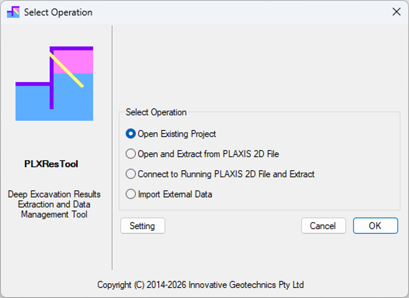
The Quick Start dialog box appears as shown in Figure 1-1, in which you can create a new project or open an existing project.

From this dialog as shown in Figure 1-2, the users can undertake the following operations:
Open Existing Project – Open an existing PLXResTool project file (*.ap2).
Open and Extract from PLAXIS 2D File – Open a PLAXIS 2D model and extract analysis results for post-processing.
Connect to Running PLAXIS 2D File and Extract – Connect directly to an active PLAXIS 2D session and extract analysis results without reopening the model.
Import External Data – Import the data file generated and saved by the program during the result extraction process.
2) Click Open and Extract from PLAXIS 2D File button
Clicking the OK button will load the file selection dialog to open the existing PLAXIS 2D project file with the file type of “*.p2dx”, as shown in the figure below.

The PLAXIS 2D Output program opens the selected PLAXIS 2D input file and automatically activates the remote scripting server using the default port (21402) and password (Password01234) settings as shown in the figure below.

2.0 PLAXIS 2D Program Setting
The PLXResTool program requires a licensed installation of PLAXIS 2D to extract results from PLAXIS 2D analysis files. The program must be configured with the installation paths for both PLAXIS 2D and the Python interpreter.
If PLAXIS 2D is installed using the default directory, the program will automatically detect the PLAXIS 2D version and the associated Python interpreter. If a user-defined installation path is used, the “User custom PLAXIS 2D and Python folder” option must be selected to specify the correct paths for use during the result extraction process.
This configuration can be defined using the “Configuration” dialog, as shown in the figure below. The dialog can be accessed by clicking the “Setting” button in the start-up dialog (see Figure 1‑2).

3.0 PLAXIS 2D Result Extraction
The following dialog appears upon successfully opening or connecting to an existing PLAXIS 2D file. Note that when using the “Open and Extract from PLAXIS 2D File” option, users must wait until the PLAXIS 2D Output program has fully loaded before initiating the extraction process. Loading time may vary depending on the computer’s hardware, and the program may open slowly on some systems.

Clicking the “Start” button initiates the result extraction process, and the extraction progress is displayed in the dialog, as shown in Figure 3‑3.

During extraction, the “Start” button is disabled and remains greyed out. It is re-enabled only after the extraction process is complete, as shown in Figure 3‑4.

Clicking the “OK” button imports all extracted data into the program and opens the “Project Properties” dialog as shown in Figure 3-5.

The following fields can be edited by the user:
Project Title – By default, this is set to the PLAXIS 2D input file name.
Job Number – The job number associated with the project.
Design Engineer – Name of the design engineer responsible for the project.
Client – Name of the project client.
Design Stage – The project design stage (e.g. preliminary design, detailed design, final design, or IFC).
Description – Additional information describing the PLAXIS 2D analysis file. This field assists in distinguishing between different analyses and is particularly useful when multiple sensitivity analyses are performed.
Clicking the “OK” button in the “Project Properties” dialog updates the main program interface with the imported data, as shown in Figure 3‑5. The extracted dataset includes analysis results for all plate elements and node-to-node anchor elements across all analysis stages within the PLAXIS 2D model.
Figure 3-6 shows the program interface after the extracted data has been successfully imported into the program. The top-left panel lists all analysis stages, while the bottom-left panel displays the user-defined vertical plates.
The right-hand section of the main window contains three tabs:
Plates – Displays all plate elements extracted from the PLAXIS 2D model.
Geometry – Displays the extracted plate elements in the global X (horizontal) and Y (vertical) coordinate system, as shown in the Figure 3-7.
Mesh – Displays the finite element mesh and connectivity information extracted from the PLAXIS 2D model, as shown in the Figure 3-8.
These tabs provide different views of the extracted model data and facilitate the review of plate element geometry, mesh configuration, and analysis results.


4.0 Defining Retaining Wall Plate Elements
After successfully extracting PLAXIS 2D results (including plate and node-to-node anchor elements), users must define or select the relevant retaining wall plate elements to obtain the associated detailed results for both plate and anchor elements.
Only vertical plate elements sharing the same X‑coordinate are available for selection. The program automatically identifies all node‑to‑node anchor elements connected to the selected plates. In deep excavation applications, node‑to‑node anchors are commonly used to represent either horizontal struts supporting the retaining wall or the inclined free‑length portions of ground anchors behind the wall.
In the “Plates” tab, left‑clicking on a vertical plate selects all plate elements with the same X‑coordinate. The selected plate is highlighted in red. Right‑clicking opens a context menu, from which the “Add Plate” option can be selected as shown in the figure below.

Clicking the “Add Plate” menu item opens the “Add Plate” dialog as show in the Figure 4-2.
The X‑coordinates of the selected plate elements are automatically displayed in the “X Coord (m) for Start Point” and “X Coord (m) for End Point” fields. As only vertical plates are selected, the X‑coordinate values for the start and end points are identical by default. Note that all the X-coordinate values are read only and cannot be modified by users
The Y‑coordinate for the start point is automatically set to the minimum Y‑value of the selected plate elements, while the Y‑coordinate for the end point is set to the corresponding maximum Y‑value. Users may modify the Y‑coordinate values if only a portion of the vertical plate, rather than its full length, is required for result processing. The default plate name is “New Vertical Plate at X = [X‑coordinate value]”. This name can be modified by users.


Clicking the “OK” button in the “Add Plate” dialog updates the plate list in the lower-left tab of the program. Note that a maximum of 10 plates can be defined in the program.
Vertical plate inputs can be modified by users via the “Edit Plate” toolbar button or through the “Edit Plate” option under the “Define” menu. This opens the “Edit Plate” dialog as shown in the figure below. This dialog provides additional input parameters as below required for stress calculations of soil and water pressures acting both behind and in front of the selected plate:
Stress Node Number – The number of nodes along the selected plate for stress and water pressure calculation based on the extracted PLAXIS 2D results. The default value is 100.
Position Tolerance – The tolerance value used to create the cross section lines behind and in front of the selected plate to extract the soil and water pressure. By default, a tolerance value of 0.050 m is adopted.

5.0 Post-Processing Extracted PLAXIS 2D Results
After extraction and import of all PLAXIS 2D results (including plate displacements and forces, node-to-node anchor forces, and soil and water pressures), the data can be further processed for the selected vertical plates (retaining walls) as defined in the Section 4. Clicking the “Run” button on the toolbar initiates the post-processing of the analysis results, as show in the figure below.

For each plate specified in the user-defined plate list, the program calculates deflections, bending moments, shear forces, axial forces, as well as soil and water pressures on both the left and right sides.
The calculation of plate results eliminates duplicated values at shared nodes. In the original PLAXIS 2D output, plate results are element-based; consequently, nodes located at the interface between adjacent elements may contain duplicated results. The PLXREsTool identifies such coincident nodal data and removes duplicate values, thereby ensuring a consistent, unique set of nodal results for subsequent analysis and reporting.
The calculation of soil and water pressures is undertaken based on the defined number of stress nodes, as specified in the Section 4. The selected vertical plate member is discretised into equal segments corresponding to the stress node configuration. At each stress node, soil and water pressures are determined using the extracted soil stress and pore water pressure results from PLAXIS 2D.
This methodology ensures that the calculated soil and water pressure distributions are consistent with the original PLAXIS 2D results, while enabling the development of a continuous pressure profile along the retaining wall. Pressure values are obtained for each node on both the retained (back) and exposed (front) sides of the wall.
It should be noted that, in the original PLAXIS 2D output, soil stress and water pressure values on either side of the selected vertical plate are derived from different nodal positions. This is due to the section line used for stress extraction intersecting the triangular finite element mesh on both sides of the plate, such that no single node simultaneously represents results on both sides of the wall.
The adopted methodology enables the determination and reporting of net pressures at any point along the selected vertical plate. The resulting soil and water pressure outputs are presented in a simplified and standardised format, facilitating direct implementation in structural models. This format is compatible with common structural analysis software and can be readily imported for subsequent structural assessment.
Upon completion of the post-processing of PLAXIS 2D results, the PLXResTool viewer will be automatically launched to display all results, as discussed in the following chapter.
During this process, all input toolbar buttons will be disabled (greyed out), and no further modifications to the inputs can be made unless the input file is unlocked. Upon unlocking, all post-processed data, including plate results as well as soil and water pressure outputs, will be deleted.
6.0 PLXResTool Viewer for Extracted PLAXIS 2D Results
The PLXResTool viewer, as illustrated in the figure below, will be automatically launched upon completion of the post-processing of PLAXIS 2D analysis results.

The PLXResTool viewer comprises three primary components:
The upper-left panel, which lists all PLAXIS 2D analysis stages. By default, all stages are selected, and the result plots displayed on the right include results for all stages;

Figure 6-2 PLAXIS 2D analysis stages in PLXResTool viewer The lower-left panel, which lists all defined vertical plates (retaining walls). By default, the first vertical plate is selected, and the plots correspond to this selected plate; and

Figure 6-3 Plate list in PLXResTool viewer The right-hand panel, which displays the results, include plate forces as well as soil and water pressures, for the selected vertical plate.

The following PLAXIS 2D plate results are available for the selected plate (retaining wall) defined in the input. To view a result, select the corresponding item from the “Plate” menu.
PLAXIS 2D Displacement Ux as shown in Figure 6-5.

Figure 6-5 PLAXIS 2D Displacement Ux PLAXIS 2D Bending Moment (per metre run) as shown in Figure 6-6.
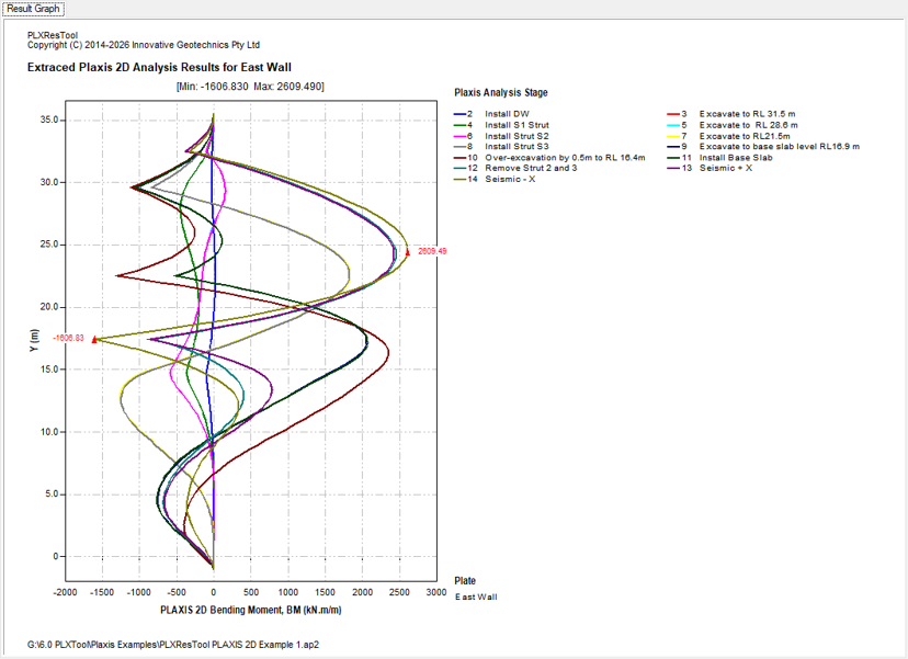
Figure 6-6 PLAXIS 2D Bending Moment (per metre run) PLAXIS 2D Shear Force (per metre run) as shown in Figure 6-7.

Figure 6-7 PLAXIS 2D Shear Force (per metre run) PLAXIS 2D Axial Force (per metre run) as shown in Figure 6-8.

SLS Bending Moment (Unfactored) as shown in Figure 6-9. This is equal to the PLAXIS 2D bending moment (per metre run) multiplied by the retaining wall spacing.

SLS Shear Force (Unfactored) as shown in Figure 6-10. This is equal to the PLAXIS 2D shear force (per metre run) multiplied by the retaining wall spacing.

SLS Axial Force (Unfactored) as shown in Figure 6-11. This is equal to the PLAXIS 2D axial force (per metre run) multiplied by the retaining wall spacing.

ULS Bending Moment (Factored) as shown in Figure 6-12. This is equal to the PLAXIS 2D bending moment (per metre run) multiplied by the retaining wall spacing and load factor.

ULS Shear Force (Factored) as shown in Figure 6-13. This is equal to the PLAXIS 2D shear force (per metre run) multiplied by the retaining wall spacing and load factor.

ULS Axial Force (Factored) as shown in Figure 6-14. This is equal to the PLAXIS 2D axial force (per metre run) multiplied by the retaining wall spacing and load factor.

7.0 Load factor and Spacing Inputs
Load factor and spacing inputs are required for the selected vertical plate (retaining wall) to calculate both the unfactored and factored retaining wall forces. Users can define the load factors and spacing values for each analysis stage independently. The spacing input is particularly important for secant piled walls and soldier piled walls, where the PLAXIS 2D results are reported per metre run of wall. For design purposes, these results must be converted into the forces acting on individual piles based on the specified pile spacing.
The Load Factor and Spacing dialog, shown in the figure below, can be opened by clicking the "Load Factor and Spacing" button on the toolbar or by selecting "Load Factor and Spacing" from the "Plate" main menu. Users can specify the load factor for each analysis stage in the "Load Factor" column and the corresponding wall spacing in the "Spacing" column.
The Load Factor and Spacing feature streamlines the post-processing workflow by automatically converting PLAXIS 2D analysis results into design values. Users can define project-specific load factors and wall spacing for each analysis stage, enabling both unfactored and factored retaining wall forces to be generated instantly. This significantly reduces manual calculations, minimises the potential for human error, and improves the efficiency and consistency of structural design and reporting.

8.0 PLAXIS 2D Node-to-node Anchor Results
The node-to-node anchor forces for the selected plate (retaining wall) are summarised in the table. These results can be accessed by clicking the “View Anchor Results” button on the toolbar or selecting “View Anchor Results” from the “Anchor” main menu. The tabulated anchor results table is shown in Figure 7-16.
The anchor results are presented in a tabulated format for each construction stage. Selecting a PLAXIS analysis stage from the list displays the corresponding anchor results for that stage.
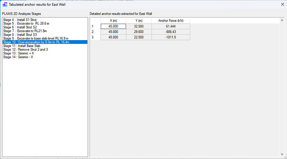
The table includes only the active node-to-node anchors associated with the selected plate (retaining wall) for the selected construction stage. The anchors are automatically sorted by their installation level (Y-coordinate) in descending order, from the highest anchor to the lowest.
Compared with the original PLAXIS 2D Output program, which lists the results for every node of each selected node-to-node anchor, this approach provides a much more concise and practical presentation of the analysis results. For deep excavation projects, engineers are generally interested only in the anchor node connected to the retaining wall, where the anchor force is transferred to the wall. By filtering out the unnecessary node results, the table is significantly simplified and easier to interpret.
Furthermore, PLXResTool stores the anchor results for all construction stages within a single project file, allowing users to switch instantly between different stages. This makes it quick and convenient to review the development of anchor forces throughout the entire construction sequence, which is particularly useful for assessing anchor loading during progressive excavation. In contrast, the original PLAXIS 2D Output program requires users to repeatedly switch between construction stages and regenerate the results, a process that can be very time-consuming for large and complex models containing many construction stages.


Comments