
LCPC CPT method for pile axial capacity in ALLCPT program
Updated: Sep 10
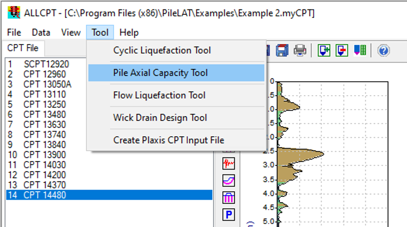
ALLCPT program provides a pile capacity analysis tool which can be used to calculate pile axial capacity for various pile types based on the imported CPT data. The pile axial capacity calculation is based on the LCPC CPT method proposed by Bustamante and Gianeselli (1982). The users can select Tool >> Pile Axial Capacity Tool from the top menu to open the pile axial capacity tool, which is shown in the figure below.
For pile axial capacity, the ultimate unit end bearing resistance fb is calculated from the equivalent average cone resistance qca which is multiplied by an end bearing coefficient Kc according to the following relationship:
The end bearing coefficient Kc can be estimated in accordance with the table below.

The equivalent average cone resistance qca is calculated based on the figure below.

In ALLCPT program, the equivalent average cone resistance qca is calculated in the following steps:
Step 1: calculate the average tip resistance qca', mean at the tip of the pile by averaging qc values over a length ranging from a=1.5D below the pile tip to a=1.5D above the pile toe (D is the pile diameter).
Step 2: Remove qc values in the zone which are higher than 1.3 times the mean of the cone tip resistance qca', mean and those are lower than 0.7 times the mean of the cone tip resistance qca', mean as shown in figure.
Step 3: Calculate the equivalent average cone tip resistance qca by averaging the remaining cone tip resistance qc values over the same zone that were not removed.
The ultimate unit side friction fs is calculated by measured qc values divided by a friction coefficient αLCPC in according to the following relationship:
The friction coefficient αLCPC can be determined by the table below:

The pile axial capacity tool in ALLCPT program is shown in the figure below. The supported pile section types are circular section, rectangular section, octagonal section, H section, Pipe Section and user-defined section.

There are seven different design approaches provided in the pile axial capacity tool and summarised as below:
Allowable working load design approach.
AASHTO (American Association of State Highway and Transportation Officials).
Eurocode 7 – UK National Annex.
Eurocode 7 – General Requirements.
Eurocode 7 – Malaysia National Annex.
Eurocode 7 – Singapore National Annex; and
Australian Standard – AS 2159 -2009.

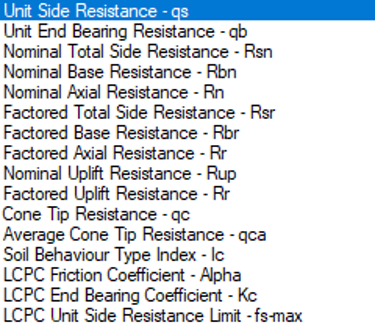
The following figure shows the typical results available for graphical plot for the design approach of "Working load design". This selection dialog can be opened with double-clicking mouse on any sub-figure. The graphical plot on that sub figure will be then updated with the selected plotting type once this selection dialog is closed.

The following figure shows the typical results available for graphical plot for the design approach of "Limit state design - AS 2159-2009".

The following figure shows the typical results available for graphical plot for the design approach of "Limit state design - AASHTO".
The Pile Result Plots tab as shown in the figure below provides a graphical presentation of the calculated pile axial capacity parameters with depth. The plots allow users to review the variation of the key design parameters adopted in the shaft and base resistance calculations and to readily identify changes associated with the CPT profile and soil conditions.

In addition to the pile axial capacity results, pile settlement under axial load is calculated based on Fleming’s approach (Fleming 1992) in ALLCPT program. The settlement results can be viewed by the users by clicking the “Pile settlement” button on the toolbar of the pile capacity analysis tool. The input parameters relevant to the settlement analysis can be input by selecting “Define > Settlement Analysis” from the “Define” menu as shown in the figure below.

The Pile Settlement Analysis Inputs dialog as shown in the figure below allows users to define the pile and soil parameters required for pile settlement analysis using Fleming’s method. Multiple pile lengths can be defined, allowing the load–settlement behaviour of piles with different lengths to be evaluated and compared within the same analysis.

The Load Settlement Curves window presents the calculated relationship between pile head axial load and pile settlement using Fleming’s approach. The load–settlement response can be generated for multiple pile lengths, allowing users to conveniently assess the influence of pile length on axial stiffness, settlement, and ultimate pile response.

Reference:
Bustamante, M. and Gianeselli, L. (1982). Pile bearing capacity prediction by means of static penetrometer. Proceedings of the 2nd European Symposium on Penetration Testing, Vol. 2, Amsterdam, The Netherlands, pp. 493–500.
Fleming, W. G. K. (1992). A new method for single pile settlement prediction and analysis. Géotechnique, 42(3), 411–425.


Comments