PileGroup Validation Examples

This validation example is based on the model test results of a group of piles embedded in sand as reported in Davisson and Salley (1970).
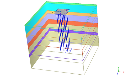
A group of six tubular aluminium piles of external diameter of 12.7 mm and wall thickness of 0.8 mm. The piles were embedded in a tank of dry fine sand to a depth of 0.533 m and loaded through a pile cap just above the level of the sand surface. The shear modulus (G) of the sand is proportional to the depth below the sand surface with the ratio of 2.4 MPa/m. The poison’s ratio for the sand is 0.25. The pile-to-cap connection was rigid for all piles.

This example is from the analysis of a 3 x 3 pile group, as documented by Pirrello and Poulos (2014). The pile group consists of piles with a diameter of 0.5 m and an individual length of 15 m. The piles are arranged with a spacing of 2 m between each pile, both horizontally and vertically.

The example of a 3 x 3 pile group in Basile (2020) is analysed using the analysis mode of linear analysis based on elastic solutions in the PileGroup program.
In this example, the piles are constructed in a homogeneous elastic soil layer with a Young’s modulus of 50 MPa and a Poisson’s ratio of 0.5. The Young’s modulus of the pile material is 30 GPa. The pile length is 20 m and the pile diameter is 1 m. The spacing between the piles is 3 m.
This example is based on the full-scale lateral load test of a 3 × 3 pile group reported by Rollins et al. (2005).
The piles were spaced at 3.3 diameters centre-to-centre and were driven open-ended into a soil profile consisting of loose to medium-dense sand underlain by clay. Each pile was a steel pipe with an external diameter of 0.324 m and a wall thickness of 9.5 mm, driven to a depth of approximately 11.5 m below the excavated ground surface.

This example is based on the full-scale lateral load test of a 3 × 3 pile group reported by Christensen (2006). The test site comprised alternating sand and clay layers.
The piles were steel pipes with an outer diameter of 0.324 m and a wall thickness of 0.0095 m. In the direction of loading, the piles were spaced at 5.65D (1.83 m) centre-to-centre, and 3.29D (1.07 m) centre-to-centre perpendicular to the loading direction. Each pile had an embedded length of 12.8 m, with the groundwater table located 2.1 m below ground level. All pile heads were connected to the pile cap with free-head conditions. Lateral loads were applied to the pile heads through a jacking system positioned 0.48 m above the ground surface to produce prescribed horizontal deflections.
Validation Example 6. Full scale static lateral load test of a 3 x 5 pile group in sand (Walsh 2005)

This example is based on the full-scale lateral load test of a 3 × 5 pile group reported by Walsh (2005). The test site comprised alternating sand and clay layers.
The piles were steel pipes with an outer diameter of 0.324 m and a wall thickness of 0.0095 m. In the direction of loading, the piles were spaced at 3.92D (1.27 m) centre-to-centre, and 3.29D (1.07 m) centre-to-centre perpendicular to the loading direction. Each pile had an embedded length of 16.6 m, with the groundwater table located 2.1 m below ground level. All pile heads were connected to the pile cap with free-head conditions. Lateral loads were applied to the pile heads through a jacking system positioned 0.48 m above the ground surface to produce prescribed horizontal deflections.

This example is based on the centrifuge lateral load test of a 3 × 4 pile group founded in loose sand reported by Zhang et al. (1999).
The model square aluminium piles were 9.5 mm wide and 304.8 mm long and located at 3-diameter spacing from one another. The centrifuge tests were conducted at 45g, which simulated prototype piles of 13.2 m in length, 0.429 m in width and embedment depth of 10.9 m in the sand. The free length, defined as the distance from the point of lateral loading to the ground surface, was measured at 2.3 m for 3 x 4 pile group installed in loose sand with fixed heads. In the centrifuge test, the unit weight was 14.05 kN/m3 for loose sand, the effective friction angle is 34.5 degree, and the coefficient of lateral subgrade reaction is 1.357 MN/m3.

This example is based on the centrifuge lateral load test of a 2 × 2 pile group founded in soft clay reported by Taghavi et al. (2014).
The piles in the groups were spaced at 7.0 pile diameters and had a 2×2 symmetrical configuration in plan and were fixed to a rigid cap placed above the ground level. The model pile was fabricated from a hollow steel tube instrumented with six pairs of strain gauges at different levels to enable bending moment measurements along the pile.

This example is based on the full-scale lateral load test of a 3 × 3 pile group reported by Rollins et al. (2003). The test site comprised stiff clays with some sand layers underlain by soft clays.
The piles were closed-end steel pipes with an outside diameter of 0.324 meters and a 12.7 mm wall thickness. They were driven to a depth of approximately 12.2 meters. The modulus of elasticity (E) for the steel was 200 GPa. The moment of inertia (I) of the pile was 1.16 x 108 mm4. To protect instrumentation, angle irons were attached to the pile, which increased the moment of inertia to 1.43 x 108 mm4. All pile heads were connected to the pile cap with free-head conditions. Lateral loads were applied to the pile heads through a jacking system positioned 0.39 m above the ground surface to produce prescribed horizontal deflections.

This example is based on the full-scale lateral load test of a 3 × 4 pile group reported by Rollins et al. (2003). The test site comprised stiff clays with some sand layers underlain by soft clays.
The piles were closed-end steel pipes with an outside diameter of 0.324 meters and a 12.7 mm wall thickness. They were driven to a depth of approximately 12.2 meters. The modulus of elasticity (E) for the steel was 200 GPa. The moment of inertia (I) of the pile was 1.16 x 108 mm4. To protect instrumentation, angle irons were attached to the pile, which increased the moment of inertia to 1.43 x 108 mm4. All pile heads were connected to the pile cap with free-head conditions. Lateral loads were applied to the pile heads through a jacking system positioned 0.48 m above the ground surface to produce prescribed horizontal deflections.
-
Ashour, M., Norris, G. M., and Pilling, P. (2002). Strain wedge model for laterally loaded piles and pile groups. Journal of Bridge Engineering, ASCE, 7(4), 245–254.
-
Basile, F. (2003). Analysis and design of pile groups. In Numerical Analysis and Modelling in Geomechanics (J. W. Bull, ed.), Spon Press (Taylor & Francis Group), Oxford, Chapter 10, pp. 278–315.
-
Basile, F. (2020). “Influence of cap rigidity on pile group design.” Piling 2020: Proceedings of the Piling 2020 Conference, British Geotechnical Association (ICE Publishing), University of Durham, UK, pp. 73–78
-
Christensen, D. S. (2006). Full scale static lateral load test of a 9 pile group in sand. M.S. thesis, Department of Civil and Environmental Engineering, Brigham Young University, Provo, Utah, USA.
-
Coffey Geotechnics. (2017). CLAP (Combined Load Analysis of Piles) User’s Manual. Sydney, Australia.
-
Davisson, M. T., and Salley, J. R. (1970). Model studies of laterally loaded piles. Journal of the Soil Mechanics and Foundations Division, ASCE, 96(SM5), 1605–1630.
-
Fayyazi, M. S., Taiebat, M., and Finn, W. D. L. (2014). Group reduction factors for analysis of laterally loaded pile groups. Canadian Geotechnical Journal, 51(7), 758–769.
-
Innovative Geotechnical Pty Ltd. (2026). PileGroup User Manual (Version 2.5): Three-Dimensional Nonlinear Finite Element Program for Pile Groups under General Loading.
-
Pirrello, S., and Poulos, H. G. (2014). “Comparison of four pile group analysis programs.” Advances in Foundation Engineering, Proceedings of the International Symposium on Advances in Foundation Engineering (ISAFE 2013), Singapore, Research Publishing Services, Singapore, 291–297.
-
Poulos, H. G. (1990). DEFPIG User’s Manual. Centre for Geotechnical Research, The University of Sydney, Australia.
-
Randolph, M. F. (2021). PIGLET: Analysis and Design of Pile Groups (Version 6.2). User Manual released June 2021.
-
Reese, L. C., and Wang, J. T. (1996). GROUP: A Computer Program for Analysis of Laterally Loaded Piles and Pile Groups. Report/Program, University of Texas at Austin, Center for Transportation Research.
-
Reese, L. C., Isenhower, W. M., and Wang, S. T. (2000). LPile Plus Version 4.0M: A Program for Analysis of Laterally Loaded Piles Using p-y Curves. Ensoft, Inc., Houston, TX.
-
Reese, L. C., & Van Impe, W. F. (2001). Single Piles and Pile Groups Under Lateral Loading. CRC Press / Balkema, Rotterdam, The Netherlands.
-
Rollins, K. M., Lane, J. D., and Gerber, T. M. (2005). Measured and computed lateral response of a pile group in sand. Journal of Geotechnical and Geoenvironmental Engineering, ASCE, 131(1), 103–114.
-
Rollins, K. M., Olsen, R. J., Egbert, J. J., Olsen, K. G., Jensen, D. H., and Garrett, B. H. (2003). Response, analysis, and design of pile groups subjected to static & dynamic lateral loads. Utah Department of Transportation Research Division Report No. UT-03.03, Brigham Young University, Provo, Utah, USA.
-
Taghavi, A., and Muraleetharan, K. (2014). “Simulating centrifuge model tests of laterally loaded pile groups in CDSM-improved soft clay using a nonlinear Winkler model.” Geo-Congress 2014: Geo-Congress Technical Papers, American Society of Civil Engineers, pp. 1254–1263.
-
Walsh, J. M. (2005). Full-Scale Lateral Load Test of a 3×5 Pile Group in Sand. M.S. thesis, Department of Civil and Environmental Engineering, Brigham Young University, Provo, Utah, USA.
-
Zhang, L., McVay, M. C., and Lai, P. (1999). Numerical analysis of laterally loaded pile groups. Journal of Geotechnical and Geoenvironmental Engineering, ASCE, 125(11), 936–946.